The Project Begins
I seperated the article into days to try to show how much work was involved in doing this project. Each "day" is based on a weekend day, maybe 8 hours of work. This will be different for every person, but it should give you an idea anyway. Other things that came up such as doing maintenance or other repairs aren't included.
At the time this article was written, the Jeep and all these modifications were untested. I am not a trained nor professional Jeep modder and as such this article may contain dangerous mods. Thus if you choose to copy any part of these mods on your vehicle, do so at your own risk as I will not be, or even feel, responsible for any loss of limb, life, money, or relationship ;)
Days 1 and 2
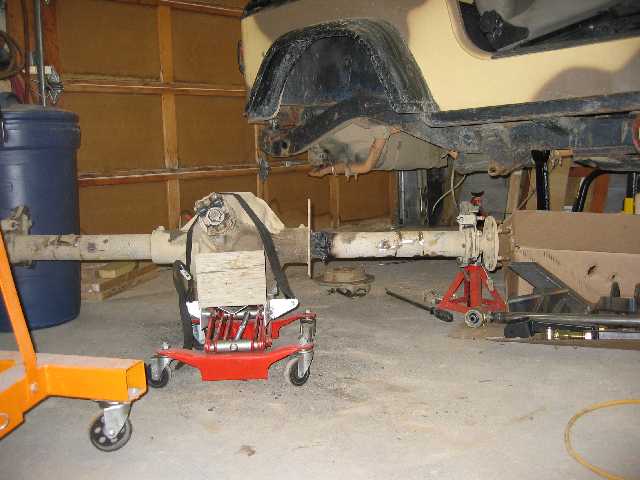
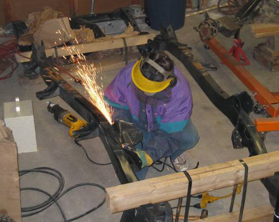
The first weekend was used to organize the garage and start tearing down the Jeep. I got the bumpers off and the rear axle out. I then got most of the rear axle brackets removed.
There's not much science to this. I mostly used an angle grinder with cutting disks to cut through the welds and a 2 lbs hammer to finish them off. The perches also had 1" of welds on the inside face which the cutting disk couldn't get through it all, so I used a sawzall to make a deeper cut. Finally the traction bar brackets are fully welded on both sides. Since I couldn't use either of the above tools on the inside weld, I cut the outside one off with an oxy-aceletyne torch and then had access to use the grinder on the inside one.
Since these axle tubes are 1/2" thick, I didn't have to worry about overheating them with the torch or tearing them when using the hammer to break the remaining welds. On axles with thinner tubes such as the stock Dana 35 and 44, more care would be needed to avoid damage.
I also took this opportunity to remove the horrible and useless drum in disk e-brakes, and the dust shields. I ordered a t-case output e-brake kit from Tom Woods which I will install later in the project.
Days 3 and 4
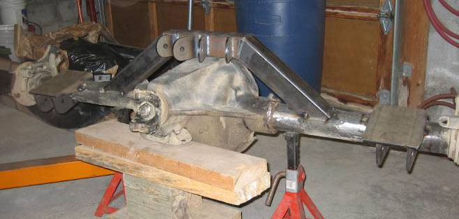
On the first day I ground off the remaining old bracket welds from the rear axle and the paint where the new brackets will go. I was now ready to tack weld the new control arm brackets. For now I only put on the flat top and lower control arm (LCA) pieces so I can test fit the suspension arms. The spring plates and shock brackets will go on after these first ones are welded on permanent.
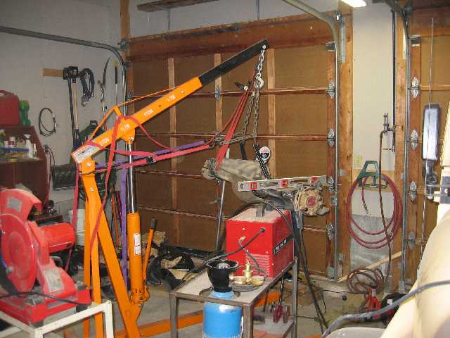
The first thing to go on is the flat top bracket. I slung the axle and lifted it with my engine hoist for convenience and set the pinion angle to 23 degrees (see the angle finder on the pumpkin below) which I had measured on my old setup before removing the axle. Then I used a level, which is far more accurate than an angle finder, to set the brackets ensuring both side will be even with each other.
The instructions only mention distance between the brackets. This is difficult to measure since when the tape bends around the pumpkin it'll add 1/4" to 1/2". I measured the distance between axle flanges which I was able to do accurately behind the cover plate. I then calculated the difference with the instruction measurements and the distance from the flange which is much easier to use.
Below the bracket are two plates to form the LCA bracket. I used one of the Johnny joints to set the proper width and get them parallel, and added a thin piece of sheet metal so the joints would slide in easily.
The upper control arm (UCA) brace that goes over the pumpkin needs to be set 11 degrees forward relative to the pinion for my setup. To make this easy I set the pinion to 11 degrees and used a level to set the brace. It also needed to be centered laterally, they provide a punch mark on the brace, and again I used the axle flanges to make my measurements.
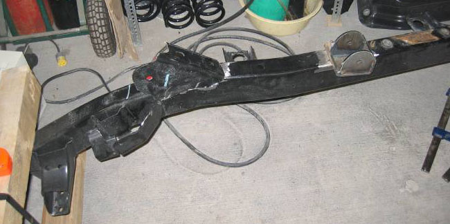
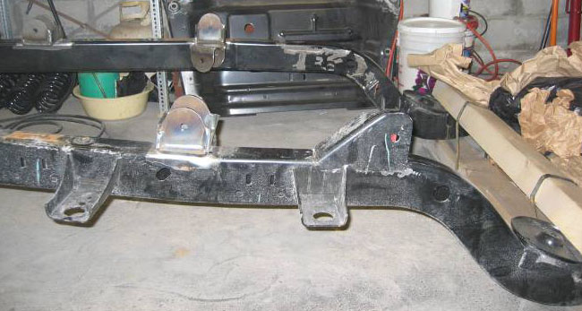
Now that the axle was done I moved to the frame. I started by cutting the original front and rear LCA brackets off. I also removed the rear UCA brackets even though the instructions don't require this, I just thought they might get in the way later. Besides grinding the welds off, I cut the brackets in half with a sawzall to make them easier to break off. I ground the remains down, ground the paint off where the new brackets will go, and also needed to drill out the two rear skid plate frame nuts. The nuts fell inside the frame so I fished them out using a magnetic wand.
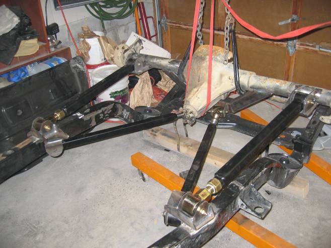
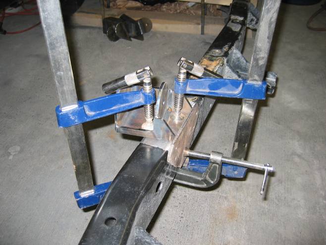
The control arm brackets are easy to install following Clayton's instruction. I just needed lots of clamps, measured many times to ensure both sides were equal, and I tack welded them in place. The plate clamped on the side is used to align the bracket.
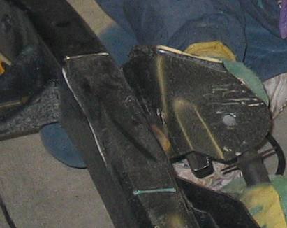
Below you can see the difference in the bracket locations from stock to Clayton's.
It was finally time to test fit the rear axle. Another nice thing about the Clayton kit is the threads on the control arms have anti-seize, I've never seen other companies do this. But on a small downside, Clayton expects you'll reuse some of your old bolts so there's a couple missing here and I have to run to the store. If it looks kinda funny, it's because the frame is still upside down ;)