Build Project - SS Cherokee

mucovich

Till Valhalla!
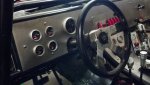
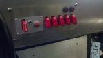
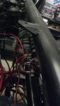
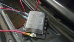
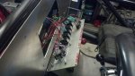
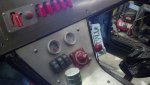
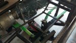
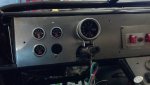
Started wiring up the switch panel and mounted the first two gauges, a lot more wiring to go!
 

Attachments

  • 2015-03-19_13-08-54_5511_zpszk4ebdkm.jpg
    2015-03-19_13-08-54_5511_zpszk4ebdkm.jpg
    134.5 KB · Views: 23
  • 2015-03-19_13-09-14_7101_zpsvpccljjg.jpg
    2015-03-19_13-09-14_7101_zpsvpccljjg.jpg
    156.9 KB · Views: 23
  • 2015-03-19_13-09-31_5582_zpsackffcaz.jpg
    2015-03-19_13-09-31_5582_zpsackffcaz.jpg
    162.3 KB · Views: 22
  • 2015-03-19_13-13-32_5511_zpspbvcfjzc.jpg
    2015-03-19_13-13-32_5511_zpspbvcfjzc.jpg
    175.6 KB · Views: 24
  • 2015-03-19_16-01-47_5401_zpsb0g0yxvq.jpg
    2015-03-19_16-01-47_5401_zpsb0g0yxvq.jpg
    171.3 KB · Views: 27

mucovich

Till Valhalla!
Got a bunch of little things done today - finished installing the cable for the tranny shifter and shifts smooth like butter. Framed in the floor with some square tubing and made up a bunch of tabs from some flat stock I had for the aluminum panels (I've started making cardboard templates) and placed the rad in the rear to get a visual of how it will sit - will be a few inches higher than it sits now to get some airflow over top of the fuel cell.
 

Attachments

  • 2015-04-03_11-37-03_62_zpspdnm1pcz.jpg
    2015-04-03_11-37-03_62_zpspdnm1pcz.jpg
    190.9 KB · Views: 25
  • 2015-04-03_12-39-21_841_zpskjqds9be.jpg
    2015-04-03_12-39-21_841_zpskjqds9be.jpg
    178.9 KB · Views: 24
  • 2015-04-03_13-37-24_176_zpsloou2jby.jpg
    2015-04-03_13-37-24_176_zpsloou2jby.jpg
    169.8 KB · Views: 24
  • 2015-04-03_14-18-37_6_zpsfyidq4af.jpg
    2015-04-03_14-18-37_6_zpsfyidq4af.jpg
    204.8 KB · Views: 24
  • 2015-04-03_16-48-53_890_zpsx2qc4jd1.jpg
    2015-04-03_16-48-53_890_zpsx2qc4jd1.jpg
    200.4 KB · Views: 25

mucovich

Till Valhalla!
Filled the transmission and finished all the floor/console cardboard templates, the vacancy in front of the transmission will soon be occupied! This coming week my plan is to install the rest of the gauges, and modify my fuel pump to support a return fuel injection system. I'll be running an MSD fuel regulator close to the fuel rails and run -6 lines throughout. It's nice to be checking the boxes of a bunch of the small things!
 

Attachments

  • 2015-04-04_18-49-13_8221_zpsrtoek1tf.jpg
    2015-04-04_18-49-13_8221_zpsrtoek1tf.jpg
    209.5 KB · Views: 25

mucovich

Till Valhalla!
I got a few more things done today, mounted a few more gauges, empty hole is for a fuel gauge (don't have it yet) and mocked up where the tach will sit. I also converted my Chrysler fuel pump to non regulated by removing the fuel regulator and installing the conversion by Novak Adapters and plumbed in a return line. This will give me 60 psi which I will regulate at the fuel rails. I also started installing ignition components, so there are wires everywhere!

This is removing the stock regulator and disassembling the fuel pump.
 

Attachments

  • 2015-04-06_14-05-27_263_zpsz9tyljtc.jpg
    2015-04-06_14-05-27_263_zpsz9tyljtc.jpg
    173.6 KB · Views: 13
  • 2015-04-06_14-05-44_962_zpseweyty4l.jpg
    2015-04-06_14-05-44_962_zpseweyty4l.jpg
    155.8 KB · Views: 13
  • 2015-04-06_14-18-14_506_zpsaw9i7di0.jpg
    2015-04-06_14-18-14_506_zpsaw9i7di0.jpg
    158.6 KB · Views: 13
  • 2015-04-06_14-18-31_72_zpskz2x8eus.jpg
    2015-04-06_14-18-31_72_zpskz2x8eus.jpg
    128.7 KB · Views: 13
  • 2015-04-06_14-32-46_166_zpstffrg2hf.jpg
    2015-04-06_14-32-46_166_zpstffrg2hf.jpg
    114.5 KB · Views: 13

mucovich

Till Valhalla!
Then I installed the adapter and plumbed in the return line, and mounted the gauges.
 

Attachments

  • 2015-04-06_15-19-55_731_zpshb0afvkc.jpg
    2015-04-06_15-19-55_731_zpshb0afvkc.jpg
    167.7 KB · Views: 14
  • 2015-04-06_15-08-27_221_zpsa5luq8pt.jpg
    2015-04-06_15-08-27_221_zpsa5luq8pt.jpg
    162.2 KB · Views: 14
  • 2015-04-06_12-18-03_194_zpshlbbtmbk.jpg
    2015-04-06_12-18-03_194_zpshlbbtmbk.jpg
    156 KB · Views: 14

Kunker

Administrator
Club Member
Filled the transmission and finished all the floor/console cardboard templates, the vacancy in front of the transmission will soon be occupied! This coming week my plan is to install the rest of the gauges, and modify my fuel pump to support a return fuel injection system. I'll be running an MSD fuel regulator close to the fuel rails and run -6 lines throughout. It's nice to be checking the boxes of a bunch of the small things!

What were you planning for on lines? Hard, braided? I picked up the PTFE stuff from Summit in hopes it'll handle the ethanol, although I still wonder if I shouldn't have used hard line as well. It just added so many more fittings, and the associated potential leak points.
 

mucovich

Till Valhalla!
I'll be running steel braided with AN fittings that I picked up the last time I was down south. Many of the after market fuel injection kits like the one I'm running state not to run hard line as cavitation can occur causing fluctuations in fuel pressure. I tried to keep all the fittings from the same brand (Russell) as I have read that mixing brands and the slight differences in tolerances between them sometimes result in leaks. I am confident in the quality of the Russell fittings that I shouldn't have a problem, I hope!
 

Kunker

Administrator
Club Member
Hadn't read that, interesting thought. Work looks awesome, can't wait to see it finished and running.
 

mucovich

Till Valhalla!
I believe the cavitation can occur in rare instances with an externally mounted pump - no worries for me but braided line makes installation easier.
 

mucovich

Till Valhalla!
Just pulled this off the MSD site and this is written in the EFI instructions...

"Do NOT use hard line when plumbing the fuel system. When using a PWM fuel system, cavitation [FONT=Swis721 BT,Swis721 BT][FONT=Swis721 BT,Swis721 BT]could cause unstable fuel pressure resulting in poor engine performance."

This sounds like it can be a problem if a PWM (pulse width modulator) fuel pump controller is being used, which if i understand it correctly is a regulatorless pump - or pump that is electronically controlled to regulate it's own pressure. I ripped out all my hard line this past fall so going soft line was a no brainer for me as it will be much less restrictive especially with the HP I will be running.
[/FONT]
[/FONT]
[FONT=Swis721 BT,Swis721 BT][FONT=Swis721 BT,Swis721 BT][/FONT][/FONT]
 

junkpile

Well-known member
I gotta look further into this to make sense of it. How I understand it is you would need restriction on the inlet side of a pump in order for the pump to cavitate. I would understand a high volume pump being capable of collapsing a rubber inlet hose over a steel or plastic line and causing cavitation.
Now as far as a PWM goes it typically uses a single fuel line (no return) which could cause a pump to cavitate if the pump is trying to supply more fuel than is needed, but again that shouldn't happen because the pump has an internal bypass for such a scenario. Neither situation should prefer a rubber hose over a steel/plastic line. Rubber is also more apt to kink or collapse through bends...
(Sorry for chewing on this in your build thread)
http://www.stangtv.com/features/fuel-system-troubleshooting-killing-gremlins-with-aeromotive/
 
Last edited:

Kunker

Administrator
Club Member
I gotta look further into this to make sense of it. How I understand it is you would need restriction on the inlet side of a pump in order for the pump to cavitate. I would understand a high volume pump being capable of collapsing a rubber inlet hose over a steel or plastic line and causing cavitation.
Now as far as a PWM goes it typically uses a single fuel line (no return) which could cause a pump to cavitate if the pump is trying to supply more fuel than is needed, but again that shouldn't happen because the pump has an internal bypass for such a scenario. Neither situation should prefer a rubber hose over a steel/plastic line. Rubber is also more apt to kink or collapse through bends...
(Sorry for chewing on this in your build thread)

Not necessarily a restriction - heat in and of itself could cause cavitation as well, although usually it's in relation to the lower boiling point cause by the lower pressure on the suction side of the pump.

For me, I wanted soft lines around flex points - where the rails attach, pump and filter, cell. Adding more fittings to the system seemed dumb, and all braided is certainly easier to route.

Now back to your regularly scheduled tech thread :)
 

mucovich

Till Valhalla!
It is in the tank - which MSD also recomends for cooling purposes. Checked Holley - they don't talk about it much other than their fuel kits are all rubber/braided line. FAST EFI mentions using hard line in conjunction with soft but doesn't get into it either. Braided is definately easier to route and it seems that no matter what after market fuel company you look at all their fuel plumbing systems are braided. No worries on chewing this on the thread - it's been a while since my build thread caused some discussion!
 

Kunker

Administrator
Club Member
Yes! Yes! Kunker 100% true but this buggy's pump is in the tank... isn't it?

Mine (and a few others on here) are external, which is why I've been doing that research. My hopes is having the pump within inches of the tank and mounted below should help prevent any problems. I'm also running -8 to hopefully reduce the restrictions even further.
 

mucovich

Till Valhalla!
Gauges are in and I've started wiring up what I can.
 

Attachments

  • 2015-04-09_16-30-17_6751_zpsukovwof3.jpg
    2015-04-09_16-30-17_6751_zpsukovwof3.jpg
    189.5 KB · Views: 10

Function > Form

Well-known member
Club Member
Filled the transmission and finished all the floor/console cardboard templates, the vacancy in front of the transmission will soon be occupied! This coming week my plan is to install the rest of the gauges, and modify my fuel pump to support a return fuel injection system. I'll be running an MSD fuel regulator close to the fuel rails and run -6 lines throughout. It's nice to be checking the boxes of a bunch of the small things!

Looking great! Haha what parts are even still "Cherokee"???
 
Top