

|

|

|
You are using an out of date browser. It may not display this or other websites correctly.
You should upgrade or use an alternative browser.
You should upgrade or use an alternative browser.
Build Project - The Excessive Closet Juggy
- Thread starter blueguy
- Start date
blueguy
Jackstand Racer
Square tube FTW!
Shoulda just done this the first time around :smokin:
R
Root Moose
Guest
With the way you have the x-member dropping below the frame rail there will be a torque load where the beam is welded to the frame. Given the types of forces your machine is seeing I'm wondering if it might be prudent to add a gusset/stiffener tying back to the frame rail at the bottom corners of the x-members.
May be overbuilt... but given you are bending disk rotors at the transfer case (WTF?!) I'd think about something like that.
$0.02
May be overbuilt... but given you are bending disk rotors at the transfer case (WTF?!) I'd think about something like that.
$0.02
blueguy
Jackstand Racer
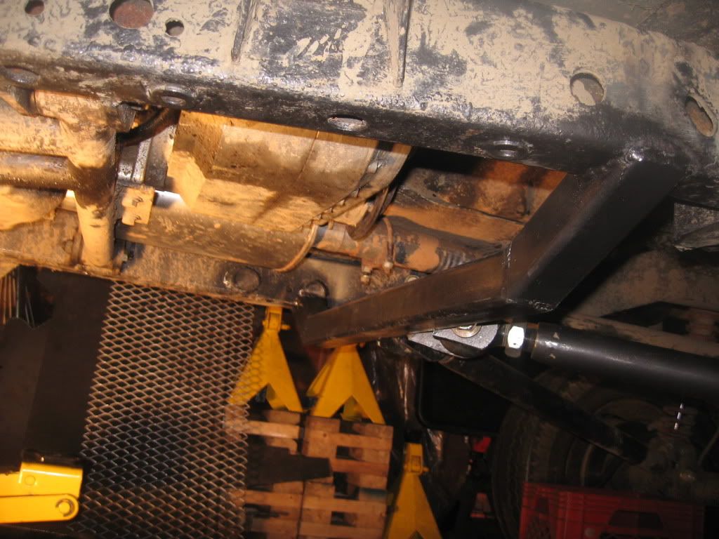
I was thinking about that already, and this is what I've come up with - I'm gonna redo the front LCA mounts and triangulate them the same way I now have the rear. The two x-members will be tied together with .188" or .25" plate that will be welded to the frame along the top and tied into the mounting "foot" for the drop-out skid I have yet to make.
If the masses get their say and Dirk's Xmas run is on the 27th, I'll be able to complete the whole thing by the middle of next week (I have boxing day commitments out of town). If the run ends up on the 28th or later, I'll probably tie the rear x-member to the frame with some square stock to counter any possible torque loading so I can wheel and then cut it out and finish it off proper like I want.
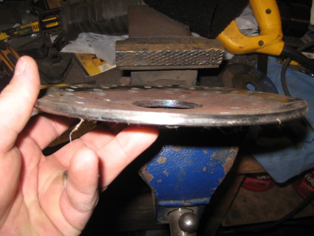
In any case, I got it all welded up and painted this morning, and managed to get the driveshaft off and survey the damage:
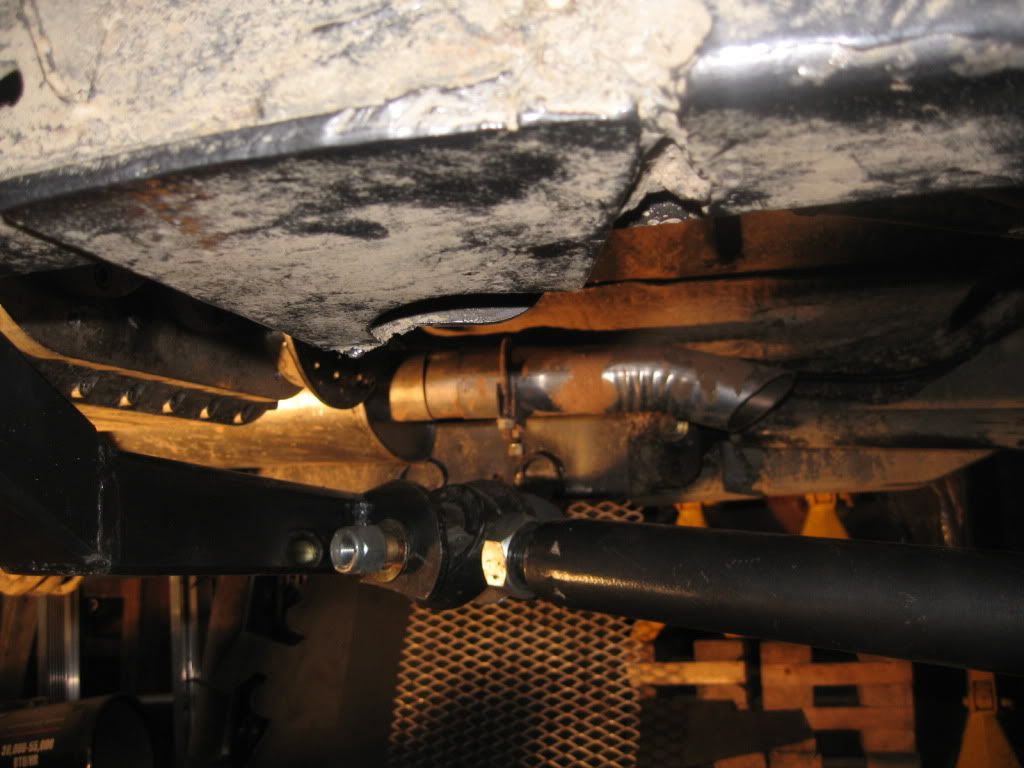
It appears that not only is the rotor bent, the inside brake pad is worn right down from the rotor being warped, but it looks like the rotor started rubbing the rear shift rail cover I might get time tomorrow to get the rear output flange off, but as it stands right now, I'm done working on this until the 27th.
If the masses get their say and Dirk's Xmas run is on the 27th, I'll be able to complete the whole thing by the middle of next week (I have boxing day commitments out of town). If the run ends up on the 28th or later, I'll probably tie the rear x-member to the frame with some square stock to counter any possible torque loading so I can wheel and then cut it out and finish it off proper like I want.
In any case, I got it all welded up and painted this morning, and managed to get the driveshaft off and survey the damage:
It appears that not only is the rotor bent, the inside brake pad is worn right down from the rotor being warped, but it looks like the rotor started rubbing the rear shift rail cover
I might get time tomorrow to get the rear output flange off, but as it stands right now, I'm done working on this until the 27th.
R
Root Moose
Guest
It appears that not only is the rotor bent, the inside brake pad is worn right down from the rotor being warped, but it looks like the rotor started rubbing the rear shift rail cover
Given that damage to the rotor I'm surprised the inside of the transfer case isn't fubar in some fashion. I think you should be pleased with anything you can get away with not having to fix.
blueguy
Jackstand Racer
I think also once a skid plate is added, it will trandfer alot of load to the front cross member. Over building is never a bad thing.
Exactly :smokin:
blueguy
Jackstand Racer
Given that damage to the rotor I'm surprised the inside of the transfer case isn't fubar in some fashion.
I'm hoping that for damage to have occurred in the case itself, the x-member would have had to hit the output shaft, kind of like a driveshaft bottoming out - but it looks like the rotor just bent back, so I'm really hoping there is nothing more to this than currently meets the eye.....
blueguy
Jackstand Racer
Didn't get a whole lot done today. Got the output flange and rotor off and had a bit better look at the rear of the case. The heads of the six allen head bolts that hold the caliper assembly bracket onto the output housing of the case have been filed down some, as has the lower right corner of the rear shift rail housing:
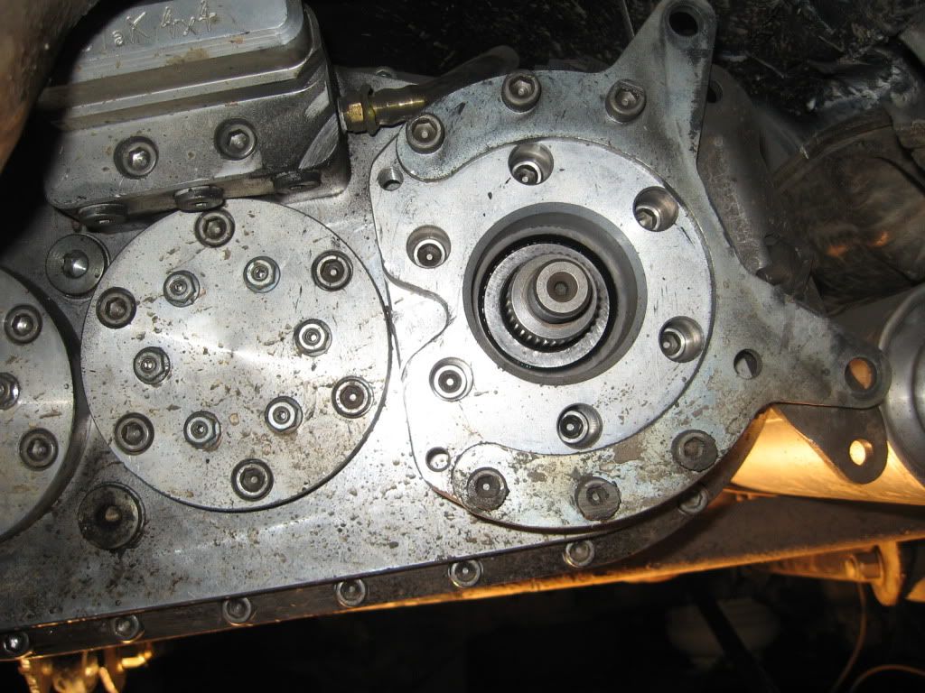
I also got a bit better look at the rotor and inside brake pad:
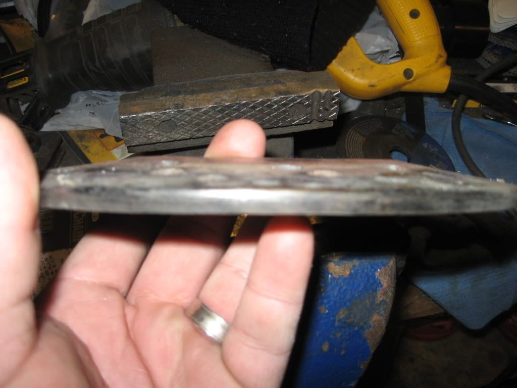
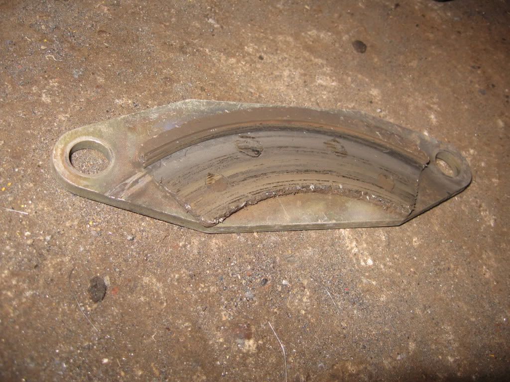
The rotor was dished pretty bad. I jammed it into my 12 ton P.A. press and flattened it out as best I could - the rotor came out pretty straight so I just reinstalled the whole shooting match with the inside brake pad upside down for the time being so there is some friction material contacting the rotor.
Other than that, I just messed around with the heater ducts in the rig. While wheeling the other weekend there wasn't a whole lot of air moving out of the ducts with the fan on high, so I decided an inspection and duct re-work was in order. I figure I'll be able to finish the duct work tomorrow and get the driveshaft back in and square off the rear end....
I also got a bit better look at the rotor and inside brake pad:
The rotor was dished pretty bad. I jammed it into my 12 ton P.A. press and flattened it out as best I could - the rotor came out pretty straight
so I just reinstalled the whole shooting match with the inside brake pad upside down for the time being so there is some friction material contacting the rotor.Other than that, I just messed around with the heater ducts in the rig. While wheeling the other weekend there wasn't a whole lot of air moving out of the ducts with the fan on high, so I decided an inspection and duct re-work was in order. I figure I'll be able to finish the duct work tomorrow and get the driveshaft back in and square off the rear end....
blueguy
Jackstand Racer
Bit of an update:
I decided once I had the rear all welded up that I might as well redo the front and finish off the skid. So, over the last week or so, I've cut the front lower link mounts out at both ends, built a new x-member for the front, readjusted the front lower link mounts at the axle end, and triangulated the lowers.
I haven't really taken any pics during the process but this is where I'm at as of tonight:
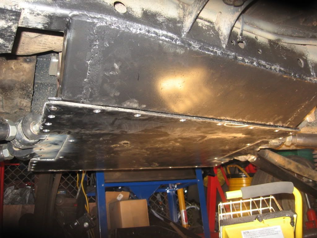
I have about another 45mins or so work until the skid and x-members are done minus the painting of the skid, but I was wondering what the general consensus is with the addition of two stringers of 1" flat plate on their ends down the centre of the drop out section of the skid itself to help support it kind of like this (looking at it from the end) | | . Or would it be just a waste of material? The skid is made from 1/4" plate, and there is about a 25" or so span between the two x-members.
BTW, did I mention how much it sucks drilling out 28 holes with a hand drill, and then trying to countersink them with the same method? :banghead: I really wish I had a bigger shop with room for either a mill or floor model drill press :baby:
I decided once I had the rear all welded up that I might as well redo the front and finish off the skid. So, over the last week or so, I've cut the front lower link mounts out at both ends, built a new x-member for the front, readjusted the front lower link mounts at the axle end, and triangulated the lowers.
I haven't really taken any pics during the process but this is where I'm at as of tonight:
I have about another 45mins or so work until the skid and x-members are done minus the painting of the skid, but I was wondering what the general consensus is with the addition of two stringers of 1" flat plate on their ends down the centre of the drop out section of the skid itself to help support it kind of like this (looking at it from the end) | | . Or would it be just a waste of material? The skid is made from 1/4" plate, and there is about a 25" or so span between the two x-members.
BTW, did I mention how much it sucks drilling out 28 holes with a hand drill, and then trying to countersink them with the same method? :banghead: I really wish I had a bigger shop with room for either a mill or floor model drill press :baby:
D
Dirk
Guest
sexy flat belly. :smokin:
R
Root Moose
Guest
... but I was wondering what the general consensus is with the addition of two stringers of 1" flat plate on their ends down the centre of the drop out section of the skid itself to help support it kind of like this (looking at it from the end) | | . Or would it be just a waste of material? The skid is made from 1/4" plate, and there is about a 25" or so span between the two x-members.
I'm not sure I'm following here.
You want to run steel "fences" on the top side of the skid that run front to back?
So two long fences that are of 1/4" plate, slightly less than 25" long, 1" tall and run at/near the edge of the belly on the top side of the plate?
Can't hurt. It'll stiffen the edges but given that your row of fasteners are at that edge I don't know if it would help much when assembled. At least not by itself and it depends on the amount of overlap at the fastened joint.
If you wanted to go "hog wild" trying to stiffen you could combine those fences with additional pieces that run from side to side to make a sort of "egg crate" arrangement but it is a lot of work for little gain. There is also the issue of driveline equipment clearances.
If there is clearance you could consider doing your fences in a "X" pattern across the plate. Where they interfere with the driveline cut out some clearance.
Just some ideas. I'd need to see the whole thing and probably think about it for, oh, 6 to 8 months before starting to cut steel. LOL
blueguy
Jackstand Racer
I'm not sure I'm following here.
You want to run steel "fences" on the top side of the skid that run front to back?
So two long fences that are of 1/4" plate, slightly less than 25" long, 1" tall and run at/near the edge of the belly on the top side of the plate?
Can't hurt. It'll stiffen the edges but given that your row of fasteners are at that edge I don't know if it would help much when assembled. At least not by itself and it depends on the amount of overlap at the fastened joint.
If you wanted to go "hog wild" trying to stiffen you could combine those fences with additional pieces that run from side to side to make a sort of "egg crate" arrangement but it is a lot of work for little gain. There is also the issue of driveline equipment clearances.
If there is clearance you could consider doing your fences in a "X" pattern across the plate. Where they interfere with the driveline cut out some clearance.
Just some ideas. I'd need to see the whole thing and probably think about it for, oh, 6 to 8 months before starting to cut steel. LOL
This is what I was doing a really bad job of trying to ask (except using 2):
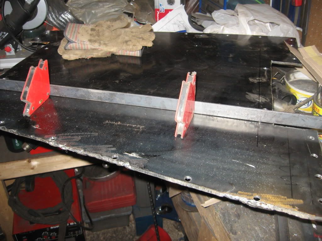
What I ended up doing was making an "X" like this:
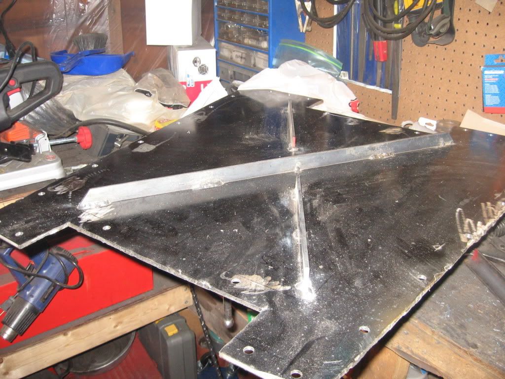
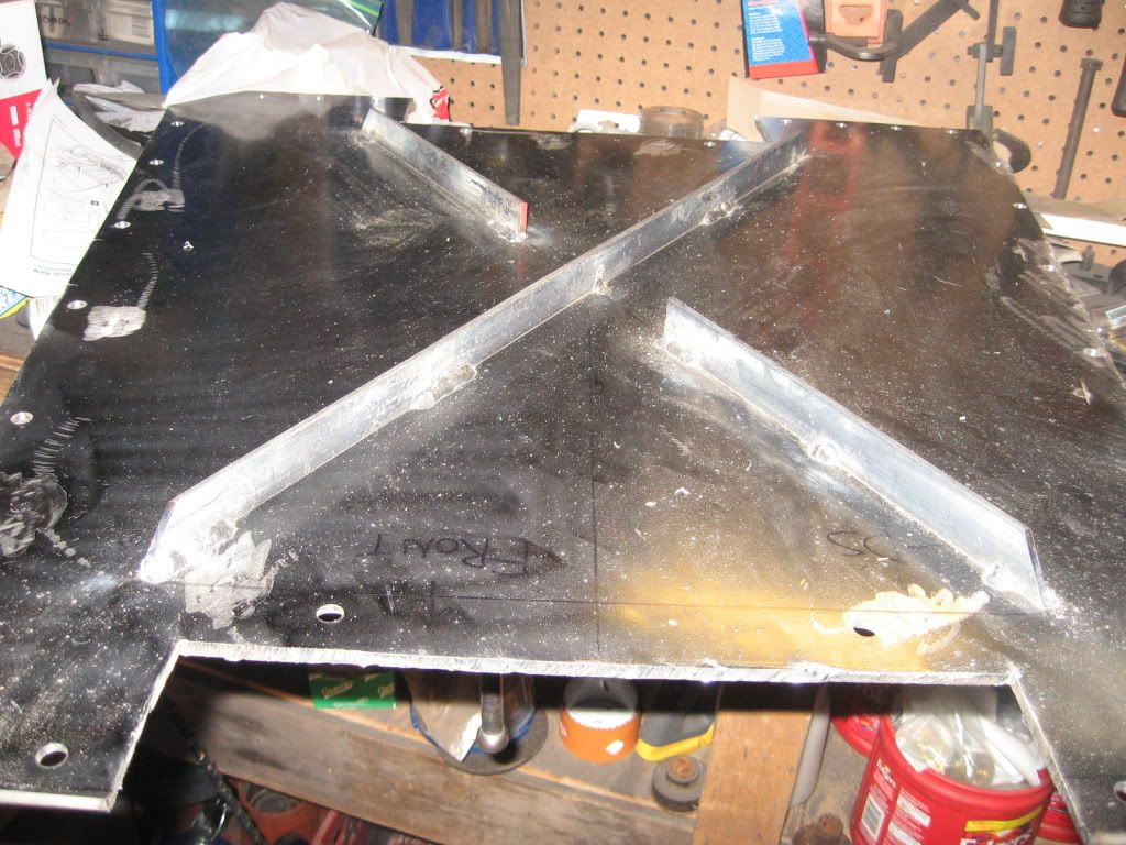
sexy flat belly. :smokin:
Skid is done and installed as of tonight:
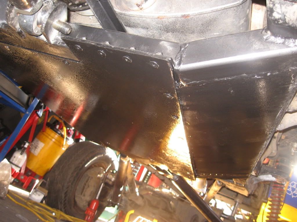
Just gotta square off both diffs, reset pinion angles and that's it for this round of repairs :smokin:
R
Root Moose
Guest
I'd be inclined to do the "X".
Think of your belly pan being made of corrugated cardboard. Now imagine it as the lid of a moving box (can relate, eh?) but only taped on two opposite sides.
Turn the box over and drop it lid first on a standing beer bottle (think rock).
What happens?
There will be a crease in the cardboard lid that runs parallel to the sides that are taped to the box. Since we are talking cardboard boxes we will have seen that the sides of the box (i.e. your frame) has a force that wants to pull into the middle of the box while this is happening.
So, what I'd do is the "X" to give the piece general stiffness and then run fences at the front and rear end of the fence running from side to side to additionally help.
Something like:
The trick comes figuring out driveline clearance per amount of steel used.
Drill some holes to ensure drainage.
$0.02
HTH
Think of your belly pan being made of corrugated cardboard. Now imagine it as the lid of a moving box (can relate, eh?) but only taped on two opposite sides.
Turn the box over and drop it lid first on a standing beer bottle (think rock).
What happens?
There will be a crease in the cardboard lid that runs parallel to the sides that are taped to the box. Since we are talking cardboard boxes we will have seen that the sides of the box (i.e. your frame) has a force that wants to pull into the middle of the box while this is happening.
So, what I'd do is the "X" to give the piece general stiffness and then run fences at the front and rear end of the fence running from side to side to additionally help.
Something like:
Code:
front

\-------/
 \     /
  \   /
   \ /
    X
   / \
  /   \
 /     \
/-------\

rear
The trick comes figuring out driveline clearance per amount of steel used.
Drill some holes to ensure drainage.
$0.02
HTH
R
Root Moose
Guest
Just noticed that you have the plate bolted at the front and rear to your cross-members.
Don't bother with the end pieces. Just put the X in there and call it done.
Don't completely weld - do a stitch weld for one inch, gap an inch, weld an inch, gap an inch, etc.
What you've got there looks massive to my non-hard-core eye but I'd still build it with best practice and try to keep as much native strength in the base material as possible. Hence the stitch weld.
blueguy
Jackstand Racer
I quasi stitch welded the "X", but just enough to more or less keep the "X" in place - the last time I braced something in this fashion, I ended up warping it from too much heat :banghead: and went a lot lighter this time around to keep that from happening
In any case, I'm gonna run it as is, and I'll modify it later on if needed :beer:
In any case, I'm gonna run it as is, and I'll modify it later on if needed :beer:
blueguy
Jackstand Racer
....I don't see the logic for leaving the 2 bits out?
There really wasn't any logic in the one side of the "X" being made of two shorter pieces - it was what I had left of the 1" flat bar, and to go to Pembroke to get more material is almost an hour return trip that I really didn't feel like doing
IMO, the gaps *shouldn't* be big enough to allow the skid to bend or crumple on a hard hit. When I started building this skid, I borrowed some ideas from the tube buggy crowd, the stock skid, and the Rubicon Express skid. I ran an RE 6" LA kit in my rig for a few years, and the drop out section of that skid is made of 1/4" plate with no reinforcing ribs down the centre (but the tranny mount is in the same spot, so maybe they expect the tranny to keep the centre of the skid from bending?)

In any case, I came down hard on that skid a few times, and it never even flinched (and the tranny never grenaded from the hits either
), so I figured my "X" would be sufficient. Now you guys have me wondering if I should drop the skid, cut out the pieces and get more 1" stock and close the gaps....In any case, I came down hard on that skid a few times, and it never even flinched (and the tranny never grenaded from the hits either
Wheel it as is. If it bends, you know what the next fix is.
Farm Boy
Bought the Farm
Spoken like true parts breaker!
:lmao: